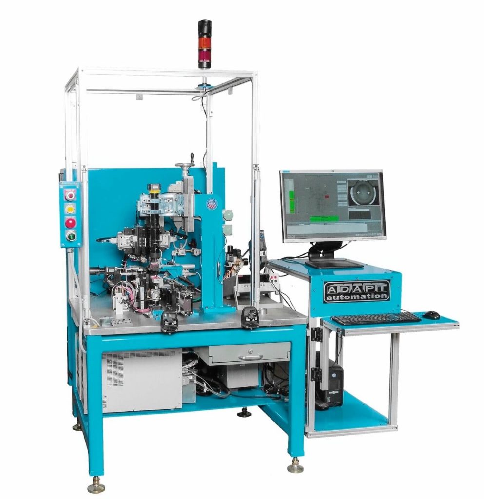
The Bridge Wire Welder will perform several types of Bridge Wire attachment methods. Our standard method and then a wire welded down inside a cavity. In each, the Header is automatically vision mapped and located for bridge wire attachment and then resistance checked at a second manually loaded station. This machine operates around a manually loaded work cell, where the operator loads the headers into a nest and activates the mapping and weld sequence. Once the wire has been attached, the operator will remove the header, visually inspect the weld and place it into an electrical test station where the resistance is checked and a disposition is placed on that particular part. If it is considered a reject, it will be automatically disposed of into a locked rejection container. If the header is considered acceptable, the operator is alerted to remove it and place it into a customer supplied packaging device for protection against damage to the welded wire.
The system is designed to accept specific styles and sizes of headers and requires a nest change where applicable. The nests are easily replaced by a single screw, yet fixtured with dowel pins to accurately line up every time. Where the method requires a welded wire down inside a cavity, the wire extends through a spring loaded roller and across the top of the header. A ring will lower done onto the wire and push it down into the sleeve and on top of the pins. There are guide rollers that hold the position of the wire in the same location every time so the weld heads always weld in the same location on the wire and pins. Once the welding has taken place, the ring elevates back up out of the sleeve, bringing the leading pigtail up with it for removal. The wire is then advanced across the next header by the wire indexing gripper to weld to the next part. For the standard method of wire attachment, two nest styles are supplied to hold the headers in the upright or vertical position for welding on the header surface, and one for holding the headers in a horizontal position for welding to the pin sides. All methods use a Cognex vision system to map the location of the glass and the pins and then uses that information to locate the wire at the specific location to achieve the correct resistance across the gap. The weld heads spread and locate to the spacing required to weld the wire accurately on both sides of the glass or gap. Where the wire is being welded to the side of the round (non flattened) pins, the weld tips are replaced with wider tips that will weld the wire to the top of the pin radius. There is no requirement for vision mapping since the weld position is determined by the position of the pins. Since the resistance of the bridge wire is totally dependent on the position of the pins on these parts, the pins are sized before welding, either in a off-line ADAPT supplied fixture before loading, or as part of the welding nest itself. For parts that require a strain relief loop in the wire, the machine will create a loop either before welding when the wire is positioned for the weld or after welding by displacing the pins, whichever engineering proves to be more practical and reliable and as agreed upon by both parties. The wire is welded independently at each location with separate upper and lower electrodes.
In each case, the pins on the opposite side of the glass seal header will be contacted by grounding electrodes in order to weld each side independently. A Weld Sentry Monitoring system is used to monitor the specified weld parameters. After welding, a separate camera provides the operator with an image on a monitor to allow them to determine the disposition of the welds before transferring it to the electrical test station. If the weld is deemed “reject” based on the visual inspection, the operator places the rejected header into an open chute that directs it to the lockable reject container. If the weld is visually acceptable, it is loaded into the nest on the adjacent electrical test station. Here, the resistance will be checked using a Keithley meter to verify the resistance across the wire. If the header is deemed acceptable, the operator will be alerted to remove the header and place it into a customer supplied protective packaging device. If the part is considered a reject, the nest will automatically release the header and discharge it into a dedicated chute that directs it to the lockable reject container.