Airbag Charge Sleeve Welder
- Home
- Automotive
- Airbag Charge Sleeve Welder
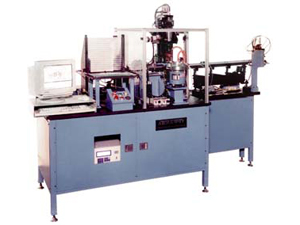
A cam driven walking beam transfers headers through a series of stations that accurately load charge sleeves on top of bridged headers and welds them in place. Each header is processed through one set of tooling, making them all very consistent with each other.
This machine is used to attach the Charge Sleeve to the Header Sub-Assembly in an Igniter. The Headers come to the machine with two pins and a Bridge Wire. A 34 station walking beam is used to progress the parts through the machine. The walking beam is driven by cams to provide controlled motion of the parts through the machine with all assemblies processed through single sets of tooling. The Headers are fed from a vibratory inline feeder which transports the oriented parts from the Bridge Wire Machine to the first station of the walking beam. At this station, a cross shuttle transfers the Header from the feeder to the walking beam track where they are taken away. The walking beam has a short transfer stroke (0.75 Inches) to allow high speeds, so there are several idle stations throughout the process.
The Charge Sleeve is fed and oriented from a vibratory feeder bowl and transferred to a vibratory inline feeder. The Charge Sleeve is then fed into a rotary transfer arm that positions it under the upper weld electrode for pick up. The weld electrode makes a short downstroke to pick up the Charge Sleeve with vacuum and then moves up to allow the transfer arm to return to the inline feeder. During the charge sleeve transfer process, the Header is advanced, located, and clamped front and back by the lower welder electrodes. The Charge Sleeve is then moved down very close to the top surface of the Header but not clamped against it yet. An alignment jaw then positions the charge sleeve accurately with respect to the Header and sets the angle to 14 degrees. The Charge sleeve is then clamped against the top of the Header and resistance welded in place. The quality of the weld is verified by a current/voltage monitor integrated into the welder power supply. After the Charge Sleeve is welded to the Header S/A the weld is further checked at station 25 by performing a nondestructive shear test and a concentricity test. At station 32, the resistance of the Bridge Wire is measured with an HP Digital Meter to verify that it was not affected by the welding process. Once the part is inspected, the good parts are pushed out of the end of the walking beam track into a tube loader and the bad parts are dropped through the walking beam track at the last station.
- Machine Number: 5648
- Cycle Rate: 30 Parts/Minute
- Controls: The control system uses an Allen Bradley PLC5 running a ladder logic program to control the real-time sequencing of the machine. Operator interface, data logging and any other interface to high-level devices is provided by a custom Microsoft Visual Basic program running on an Intel-powered PC using Windows NT Workstation 4.0 as the operating system.