Airbag Ground Pin Welder
- Home
- Automotive
- Airbag Ground Pin Welder
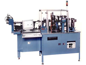
This machine is used to attach the Ground Pin to the Header Sub-Assembly in a typical Igniter. The Insulated pin is molded into a glass or ceramic insulator in the header and the ground pin is then resistance welded to the header. A 34 station walking beam is used to progress the parts through the machine. The walking beam is driven by cams to provide controlled motion of the parts through the machine. The Header S/A’s are fed from a vibratory feeder bowl into a vibratory inline feeder which transports the oriented parts to the first station of the walking beam.
At this station, a cross shuttle transfers the Header S/A from the feeder to the walking beam track where the walking beam can take it away. The walking beam has a short transfer stroke (0.75 Inches) to allow high speeds, so there are several idle stations throughout the process.
At station 5 a monochrome image of the Header S/A is acquired from below the walking beam track and the orientation of the Header S/A and true position of the tip of the insulated pin are verified by the machine vision software. If the Header S/A is not oriented properly or the pin is bent, no further operations are performed on that Header S/A and it is rejected at the end of the walking beam. At station 12 the Ground Pin is fed from a vibratory feeder bowl and is transferred into a welding electrode.
At the same time, the Header S/A is located precisely by tooling on the walking beam track and is clamped from above. The electrode containing the pin is moved under the walking beam track and raises up to clamp the ground pin against the bottom of the Header S/A. The resistance welding power supply is then fired to weld the pin in position. The quality of the weld is verified by a current/voltage monitor integrated into the welder power supply.
After the Pin is welded to the Header S/A the weld is further checked at station 25 by performing a nondestructive pull test on the pin. At station 30, a monochrome image is acquired of the tips of the two pins from the side. The machine vision software then verifies the length of the pins, the pitch between the pins, and the presence of a radius on the tips of the pins. Other features can be verified as required.
Once the part is inspected, the good parts are pushed out of the end of the walking beam track into a vibratory feeder leading to the Bridge Wire Welder and the bad parts are dropped through the walking beam track at the last station.
- Machine Number: 5644
- Cycle Rate: 30 Parts/Minute
- Controls: The control system uses an Allen Bradley PLC5 running a ladder logic program to control the real-time sequencing of the machine. Operator interface, data logging and any other interface to high-level devices are provided by a custom Microsoft Visual Basic program running on an Intel-powered PC using Windows NT Workstation 4.0 as the operating system