Automotive Header / Igniter Bridge Wire Welding Machine
- Home
- Automotive
- Automotive Header / Igniter Bridge Wire Welding Machine
- Machine Number: 5901
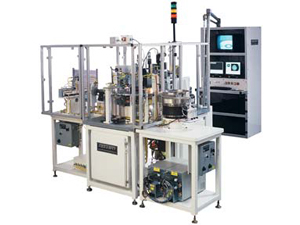
Bridgewire is precisely located, held in tension, and welded to both sides of the Header glass seal.
Headers are Vision Mapped for exact position and orientation for a .0002” accuracy, to weld the wire for proper resistance per specifications. This system produces up to 24 welded header per minute.
This machine is used to weld the Bridgewire to the Igniter Header. Headers are bowl fed from a 12” CCW feeder bowl through an inline feeder track to a dead track where the orientation of the isolated pin is checked. Headers are then placed into a height check station to verify the dimensions of the header using a dual head parts placer. Simultaneously headers are moved from the height check station to an inline feeder track and into a part orient and load station dead track. Headers are oriented as required and loaded up into a nest on a 12 station cam driven index table. Proper header orientation is verified and the headers are Vision Mapped for exact position and orientation and indexed to the weld station. At the weld station, bridgewire is spool fed and tensioned into a 16 position servo driven wire retainer turret.
The turret and weld contacts are positioned as required by the Vision Map and the bridgewire is spot welded between the isolated pin and the header substrate. Excess bridgewire is removed from the retainer turret by vacuum. After welding the Bridged Header is Vision mapped for verification of proper bridgewire placement and resistance checked to verify proper weld characteristics. Bridged headers are offloaded from the fixture through an inline feeder track to a pin height and pigtail test station where a dual head 3 position parts placer drops bad parts into a chute and transfers good parts into an inline feeder track for further conveyance down the production line track system.