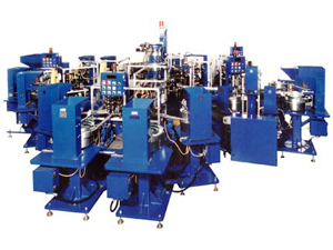
Irrigation Sprinkler Assemble and Label Machine
- Home
- Commercial
- Irrigation Sprinkler Assemble and Label Machine

- Machine Number: This system is controlled by 5 separate machine controllers, 1 for each machine, that are networked together for process synchronization.
This system of machines is used to produce a planetary gearbox used to drive an oscillating sprinkler that uses water flow as it’s power source. The Gearbox contains 24 separate parts of 12 different types. The exploded view shows how all of the parts fit together. The system is composed of 3 Sub Assembly Machine, 1 Final Assembly Machine and 1 Test Machine. The system is fully automatic, so all parts are fed from vibratory feeder bowls and are equipped with hoppers.
The system is made up of several sub assembly machines feeding one final assembly machine. This was done because the sheer number of parts in the complete assembly would make it very difficult to achieve a high assembly efficiency. If all of the parts were loaded on one machine, any failure to load any part would result in an incomplete assembly. This means that the overall efficiency of the system would be calculated by multiplying the efficiencies of each individual station. This means that if each of the 24 parts was loaded at 99% efficiency the overall efficiency of the machine would be 78%.
By splitting up the process into sub assembly machines feeding the final assembly machine with buffered storage in between, a missed gear at a sub assembly machine does not cause an incomplete assembly on the final machine. The sub assembly machines only produce parts when the buffer runs low. The sub assembly machines in this system use high speed cam index tables that have an upper tooling plate driven by the indexer that strokes vertically and oscillates radially.
The gears are fed from vibratory feeder bowls into vibratory inline feeders and are fed to positions above and in-between the fixtures on the turret. While the turret is indexing, the upper tool plate rotates 15 degrees to position the pick up tooling over the inline feeders and moves down to pick up the parts.
The upper tool plate then moves up with the part to be loaded and rotates 15 degrees in the opposite direction to position the pick up tooling over the turret fixture. By this time the turret is in the dwell position and the tool plate moves down and deposits the part in the fixture. The heart of the final assembly machine is a cam operated indexer with two overhead tooling plates.
These two plates are used to provide cam operated pick and place motions at each loading station using standard ADAPT parts placer modules. The body is loaded into the fixture on the final assembly machine and the output carrier is loaded into a detented center stem in the fixture. As each carrier sub assembly is loaded into the body, the output carrier is pressed down to the next level and the gears are meshed with the inside of the body as well as with the gear on the bottom of the carrier.
Once all of the sub assemblies are loaded, the cap & turbine are snapped on and the pinion gear is meshed with the top set of gears. The finished parts are then unloaded by a cam operated parts placer into a test machine that spins the turbine (4 up) and checks for the prescribed amount of movement of the output shaft.
