Contact-Connector Pin Insertion Machine
- Home
- Electronics
- Contact – Connector Pin Insertion Machine
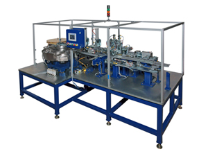
This machine operates around a walking beam type indexer for transferring the parts through the stations. The stations lock
onto the parts with hardened steel positioning plates to accurately hold them in the proper location for assembly. The insulators are vibratory bowl fed to a linear vibratory feeder that transfers them to the first station of the walking beam
indexer. The walking beam indexer comes equipped to process either the 6 or 8 pin insulators with a minimal tooling changeover.
The parts exit the end of the linear feeder, into an escapement, which shuttles them to the walking beam nest. The escapement isolates the part to be loaded from the vibrating action produced by the linear feeders. Once isolated, the
parts rest in the proper position for accurate gripping by the loading device. The pins are fed from a standard ADAPT . Automation bandolier feeder. The pins come on a reel, pre-punched to shape without the center carrier and ready to be bent
and cut from the carrier.
These pins are spaced .150” from each other with a corresponding locating hole on the carrier for each one. The feeder will use the holes in the strip to feed and locate with a sprocket. The pins are bent, cut, and inserted into the insulators in a series of steps. Bend Pins: The pins are fed into the bending station where 12 or 16 will be bent at one time.
The pins are bent in series of two side by side to the two different lengths associated with the sequence on insertion as shown below. Once the pins are bent, they are indexed to the next station where they are lowered into a cut & insert fixture. Here, every other pin is cut and inserted into the fixture.
After they are located, every other pin is inserted into the insulator. This has
now completed one insulator. The bandolier then elevates back up, lifting the remaining pins and shifts over and lowers back down, placing the second set of pins into the same cut & insert locations as the previous ones. The next insulator is brought into the station by the walking beam, and the next set of pins are cut and inserted. The bandolier then feeds through a cutting station and dispenses the scrap into a recycle container.
The pins are counted as they pass by a through beam sensor. Any
insulators without the correct amount of pins in place are ejected at the next station. Any insulator that has been deemed rejectable will be automatically removed and placed into a reject chute that directs them to a bulk storage container. All acceptable insulators are bulk off loaded into a collecting bin.
Automation standard pick & place device. The aluminum foil is reel fed to the punch and seal station. Low limit monitoring alerts the operator that the reel is running low and will need replacing soon.
The fluid is dispensed by a syringe type positive displacement pump. With a diving dispense tip that lowers into the Capsule to keep any splashing of the solution from occurring. The tubing and dispense tip are easily removable for cleaning and or replacement.
The Capsules are transferred from the feeder system and loaded into the nest by an ADAPT Automation standard pick & place device. The nest is designed to hold the Capsule in the same orientation with the hangers facing outward. The Capsules are filled by an industrial, positive displacement pump system, to ensure accurate filling has occurred. Once the vial has entered the index position, a “Y” axis diving needle lowers down into the vial to keep the liquid stable in the vial as it’s pumping in.
The Foil is automatically fed into a punch and seal station where the Foil is adhered to the top of the Capsule by a special die designed to seal and cut with a single action. The labels are fed from an ID Technology Model 252 printer that is positioned in a horizontal plane. Labels have lot and date codes printed on the standard pre-printed label. Once complete the Labels await transfer onto the Tabs that will arrive using the walking beam transfer system.